Fig
No. |
Index
No. |
S
t
o
c
k
e
d
|
Group - Fixed Equipment |
Units
per
assembly |
Blue
prints |
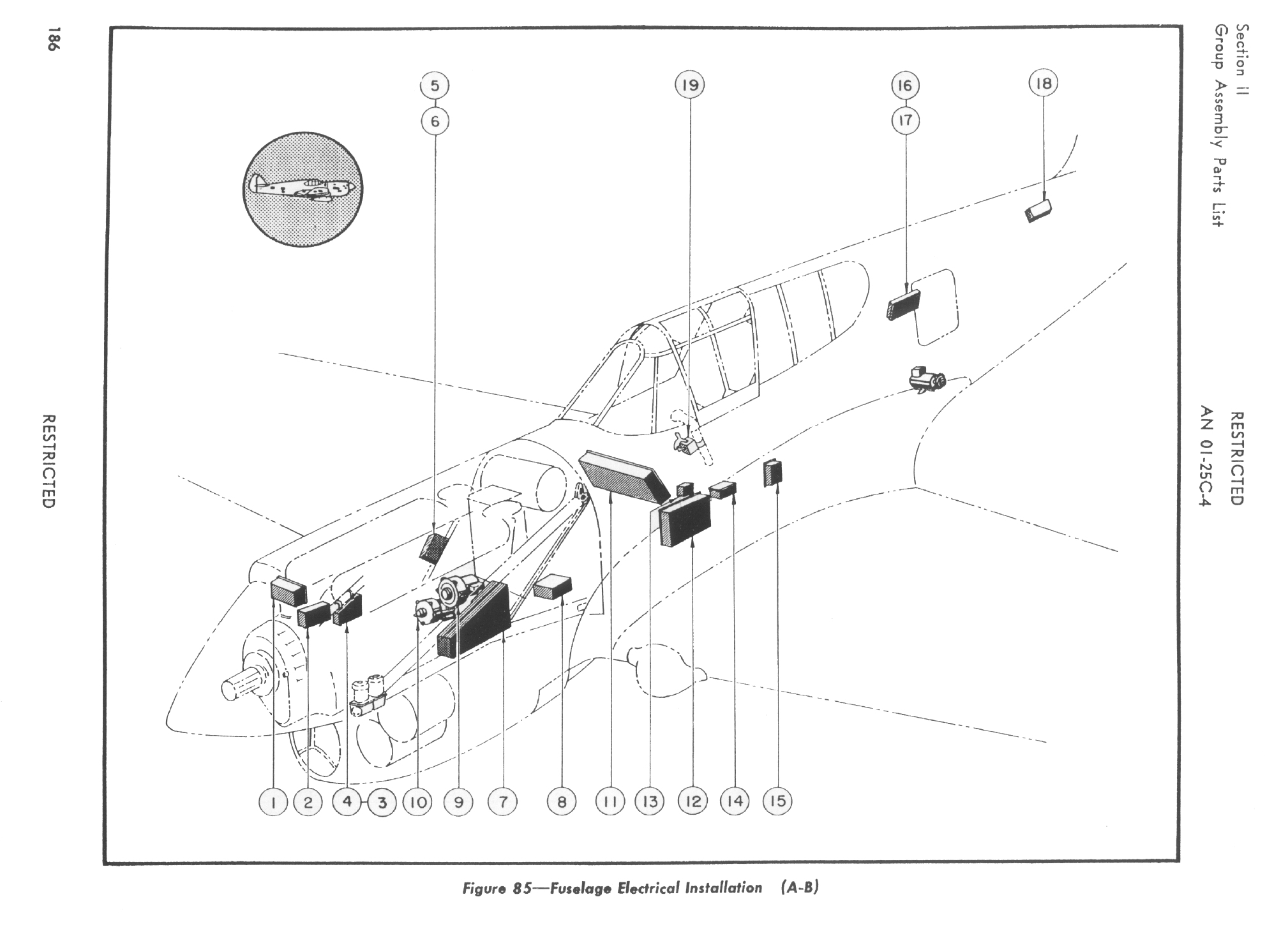
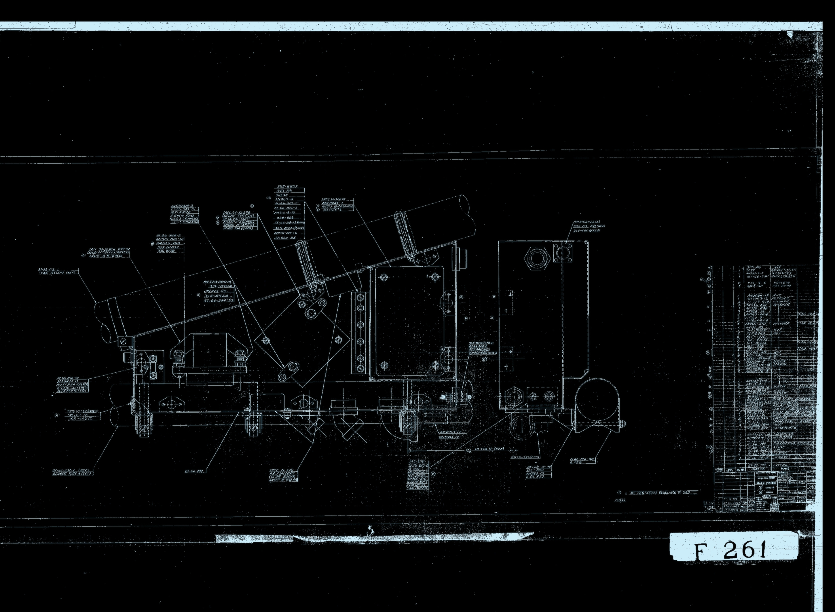
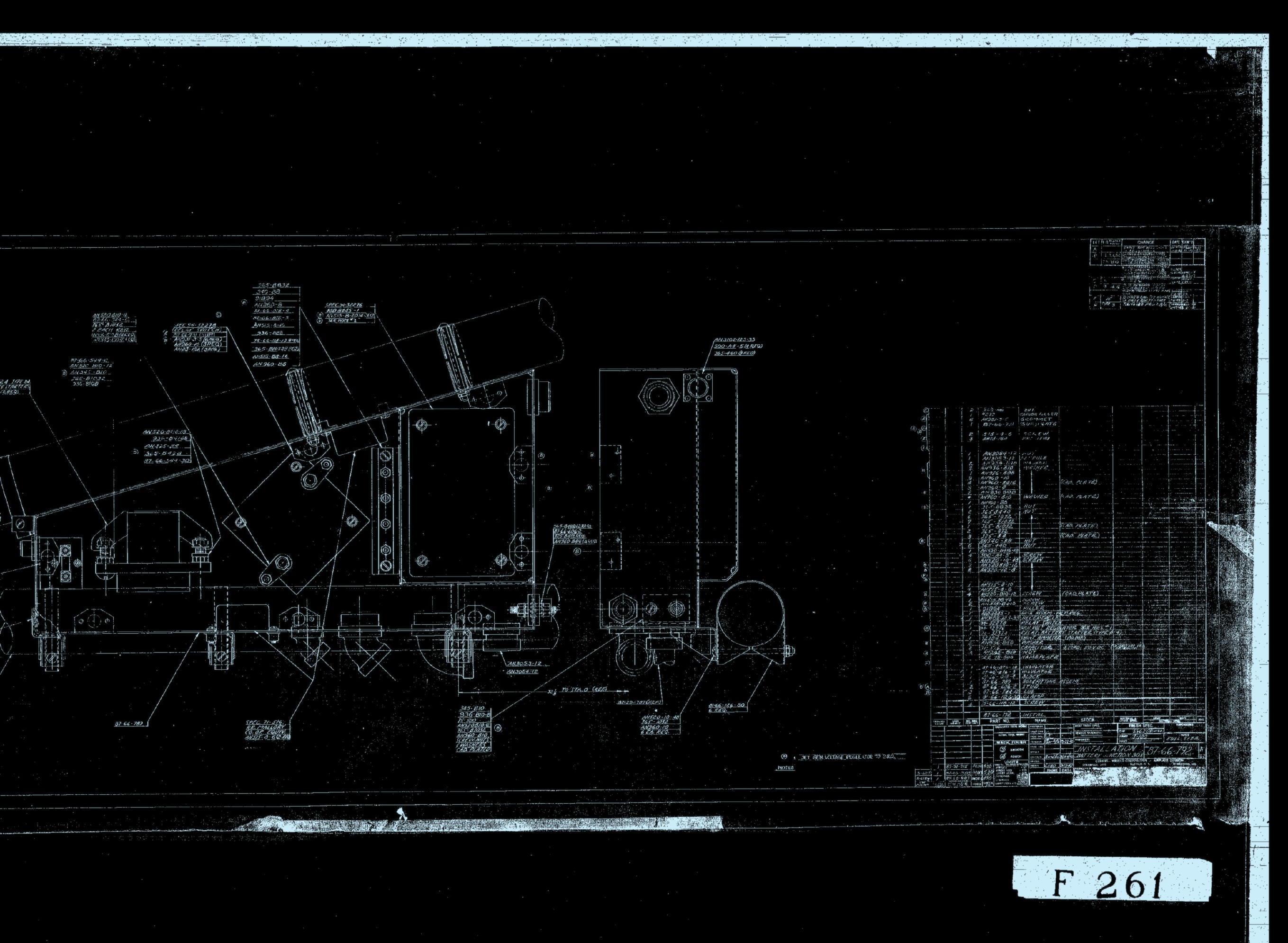
| Major Assembly - Airplane Electrical Installatoin - Fuselage Electrical Installatoin |
| Part number |
Description |
| 85 |
|
|
87-66-880 |
Electrical Installation - Fuselage |
1 |
 , , |
| 85 |
|
|
87-66-880-50 |
Electrical Installation - Fuselage |
1 |
|
| 85 |
|
|
87-66-880-100 |
Electrical Installation - Fuselage |
1 |
|
| 85 |
|
|
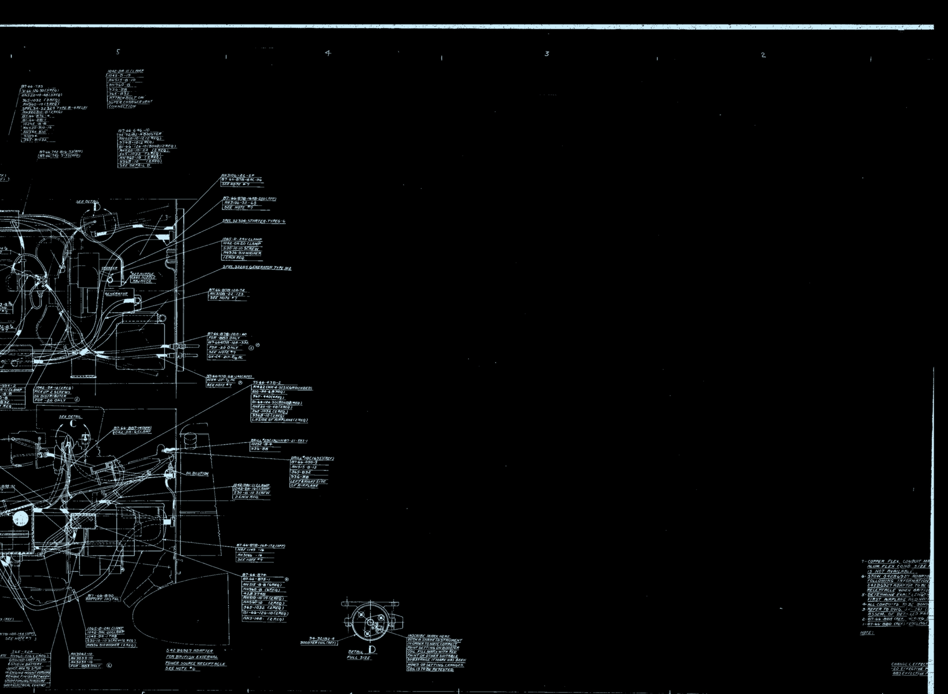
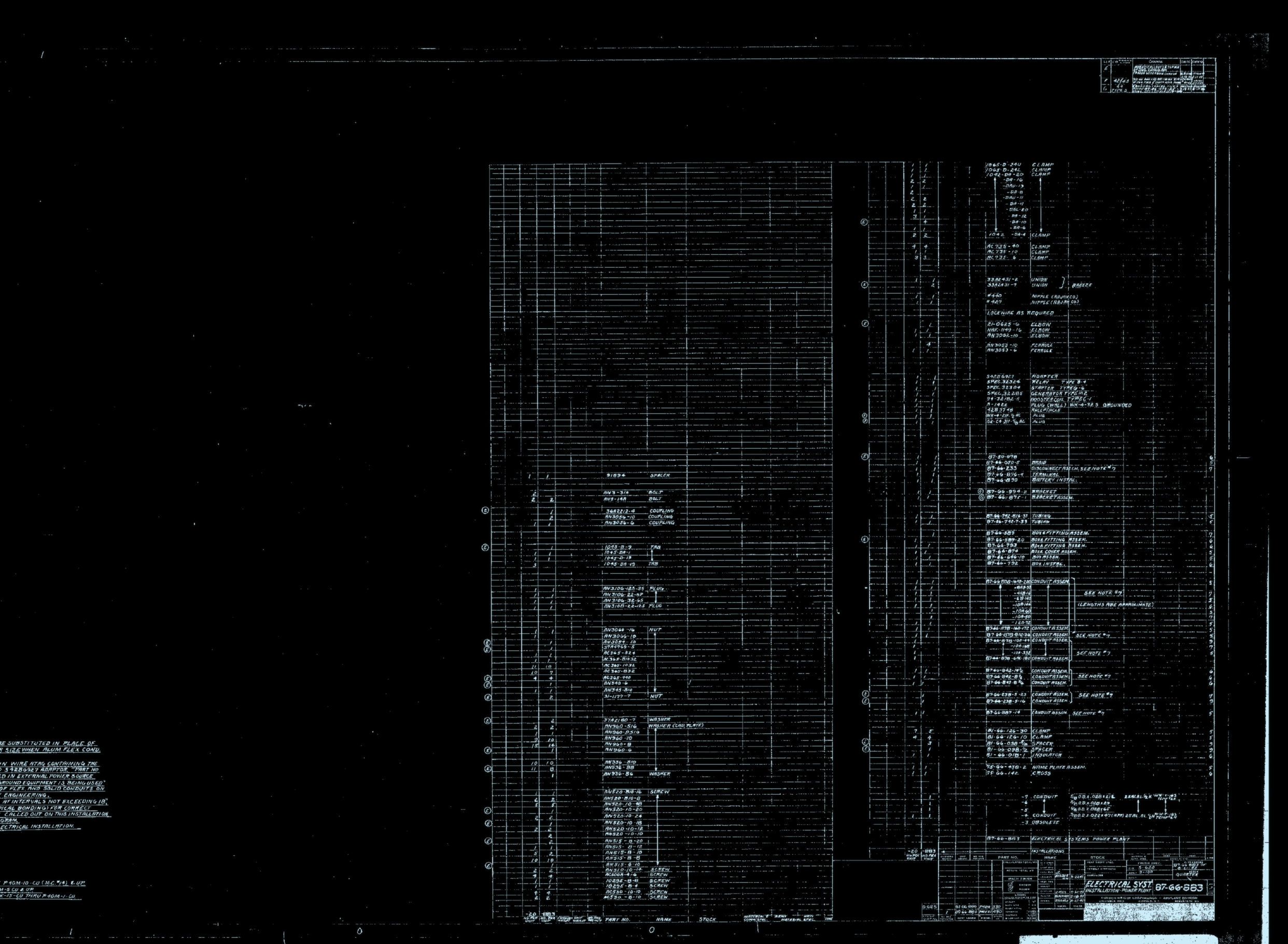
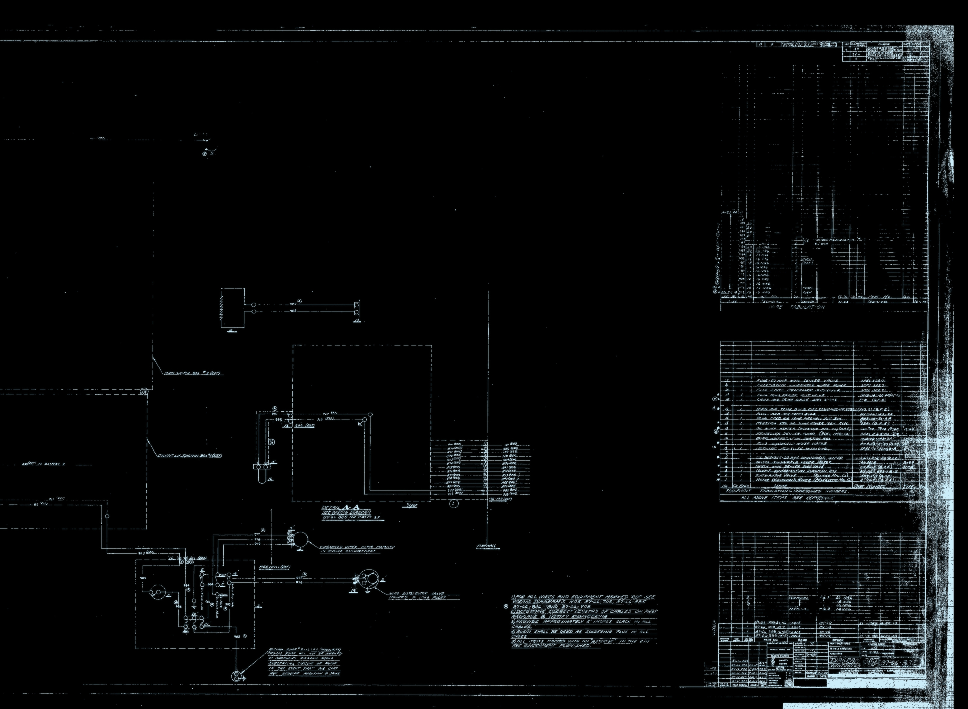
87-66-883 |
Electrical Installation - Power plant |
1 |
,, |
| 85 |
|
|
87-66-883-20 |
Electrical Installation - Power plant |
1 |
|
| 85 |
1 |
|
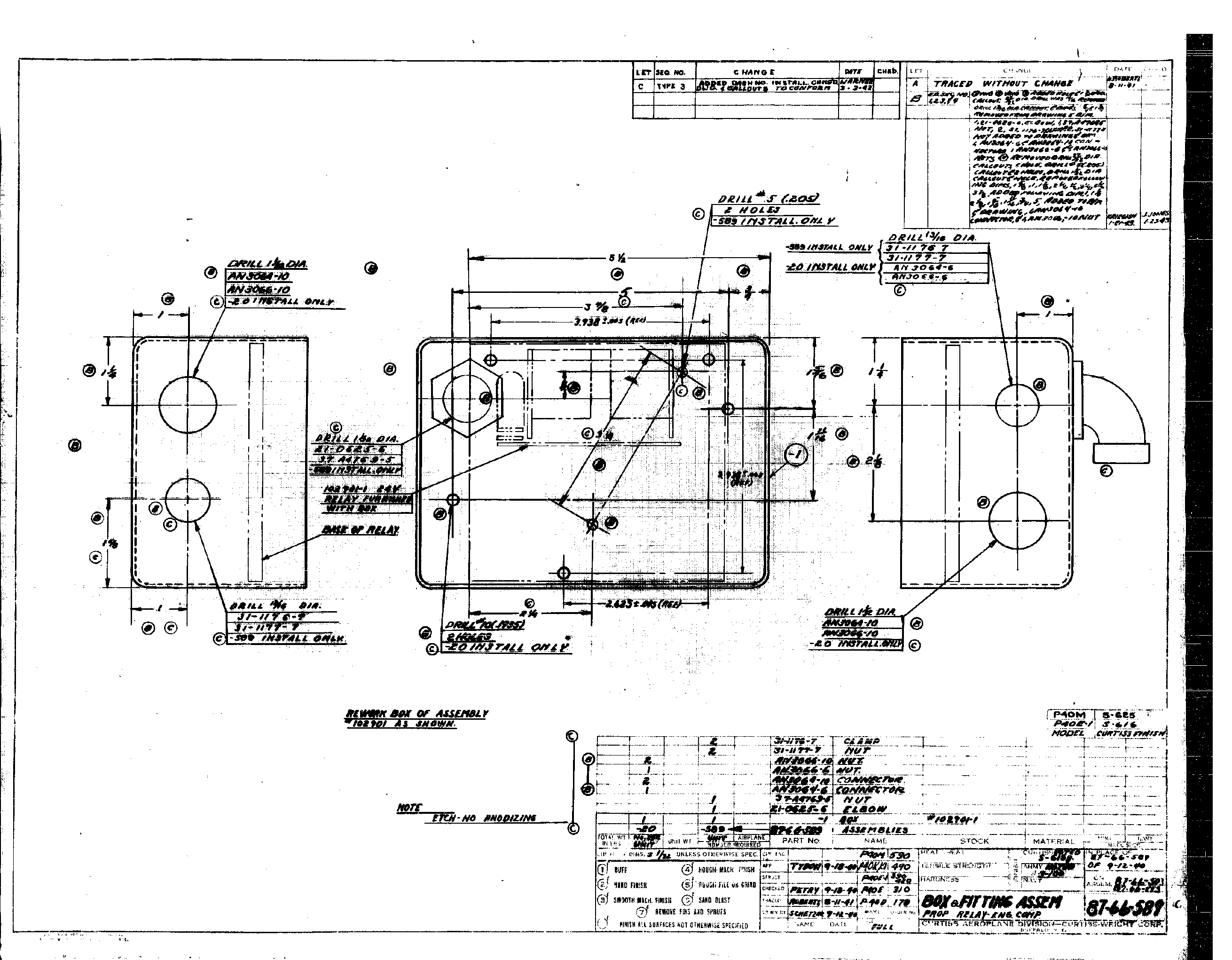
87-66-589 |
Box - Propeller relay |
1 |
|
| 85 |
2 |
|
87-66-589-20 |
Box - Propeller relay |
1 |
|
| 85 |
3 |
|
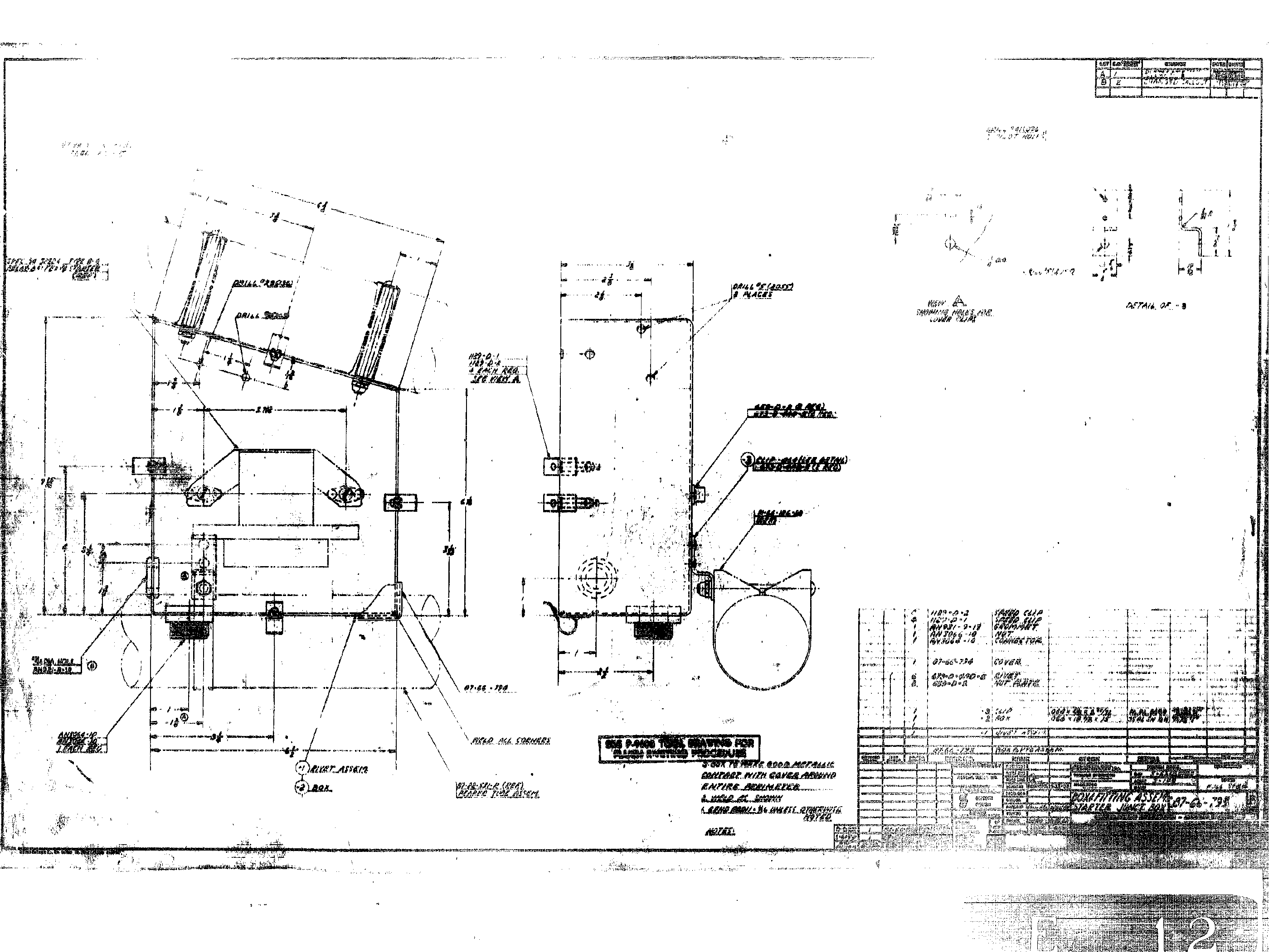
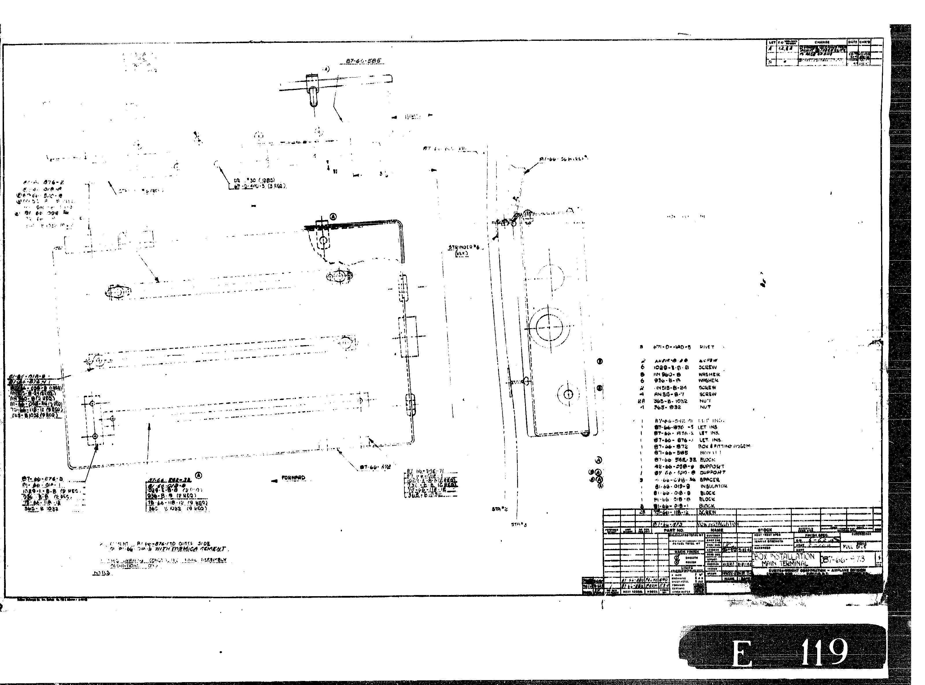
87-66-793 |
Box - Starter junction |
1 |
|
| 85 |
4 |
|
6041 H 17B |
Relay (Type B4) (Cutler - Hammer,Inc.) (GFE) (See T.O. 03-5-25) |
1 |
|
| 85 |
5 |
|
87-66-646-10 |
Box Assembly - Engine compartment |
1 |
|
| 85 |
6 |
|
93654-513-1 |
Coil - Booster (Eclipse) (GFE) (Type CA) (See T.O. 03-5-9) |
1 |
|
| 85 |
7 |
|
87-66-792 |
Box - Battery junction |
1 |
, |
| 85 |
8 |
|
87-66-874 |
Box Assembly - Battery cart plug |
1 |
|
| 85 |
9 |
|
91062-718-1 |
Generator (Type M2) (Eclipse) (See T.O. 03-5AB-1) (GFE) |
1 |
|
| 85 |
10 |
|
116455-915-4E |
Starter (Type G6) (Eclipse) (GFE) |
1 |
|
| 85 |
11 |
|
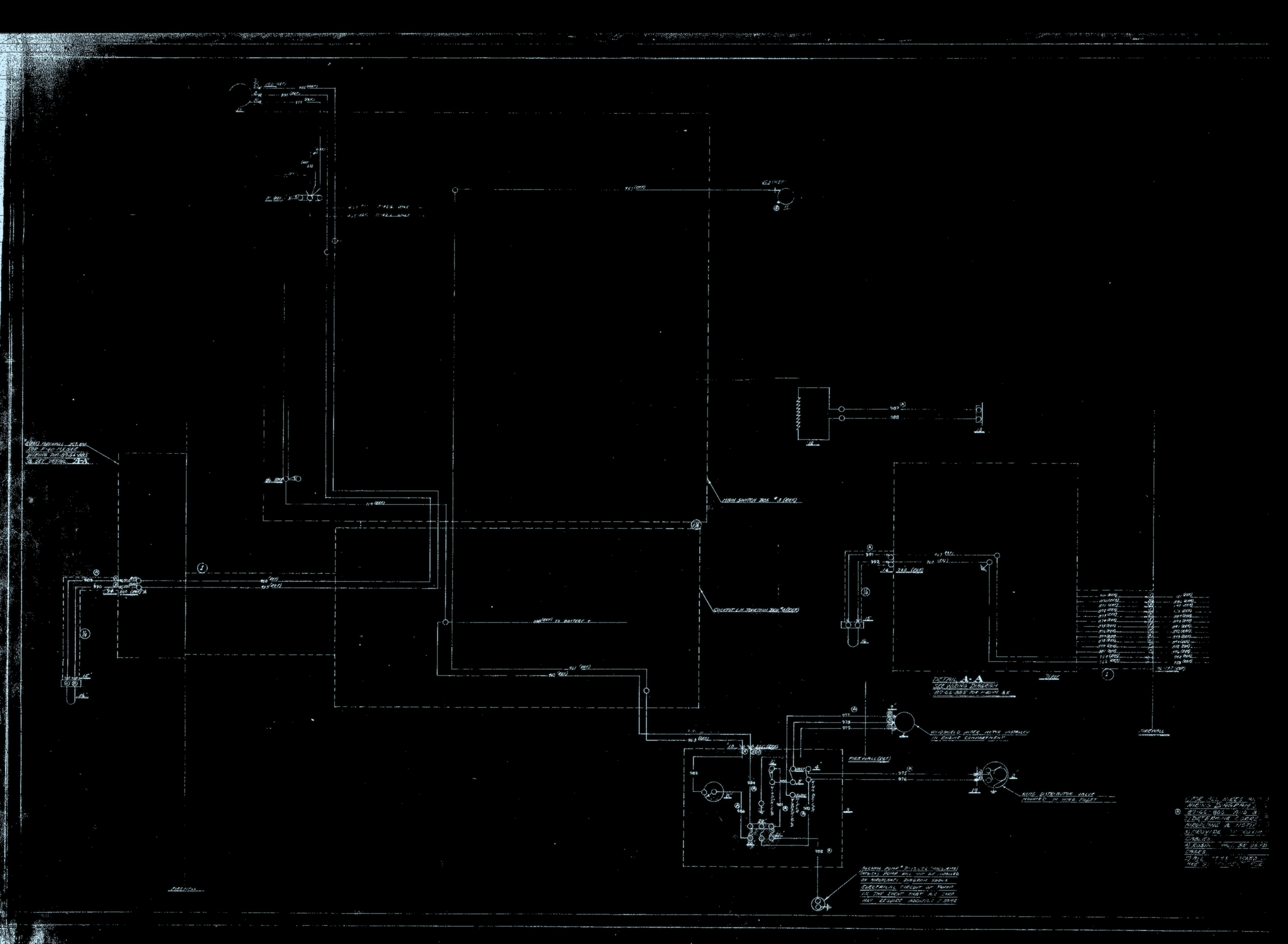
87-66-730 |
Box - Main switch |
1 |
, |
| 85 |
12 |
|
87-66-873 |
Box - Main terminal |
1 |
|
| 85 |
13 |
|
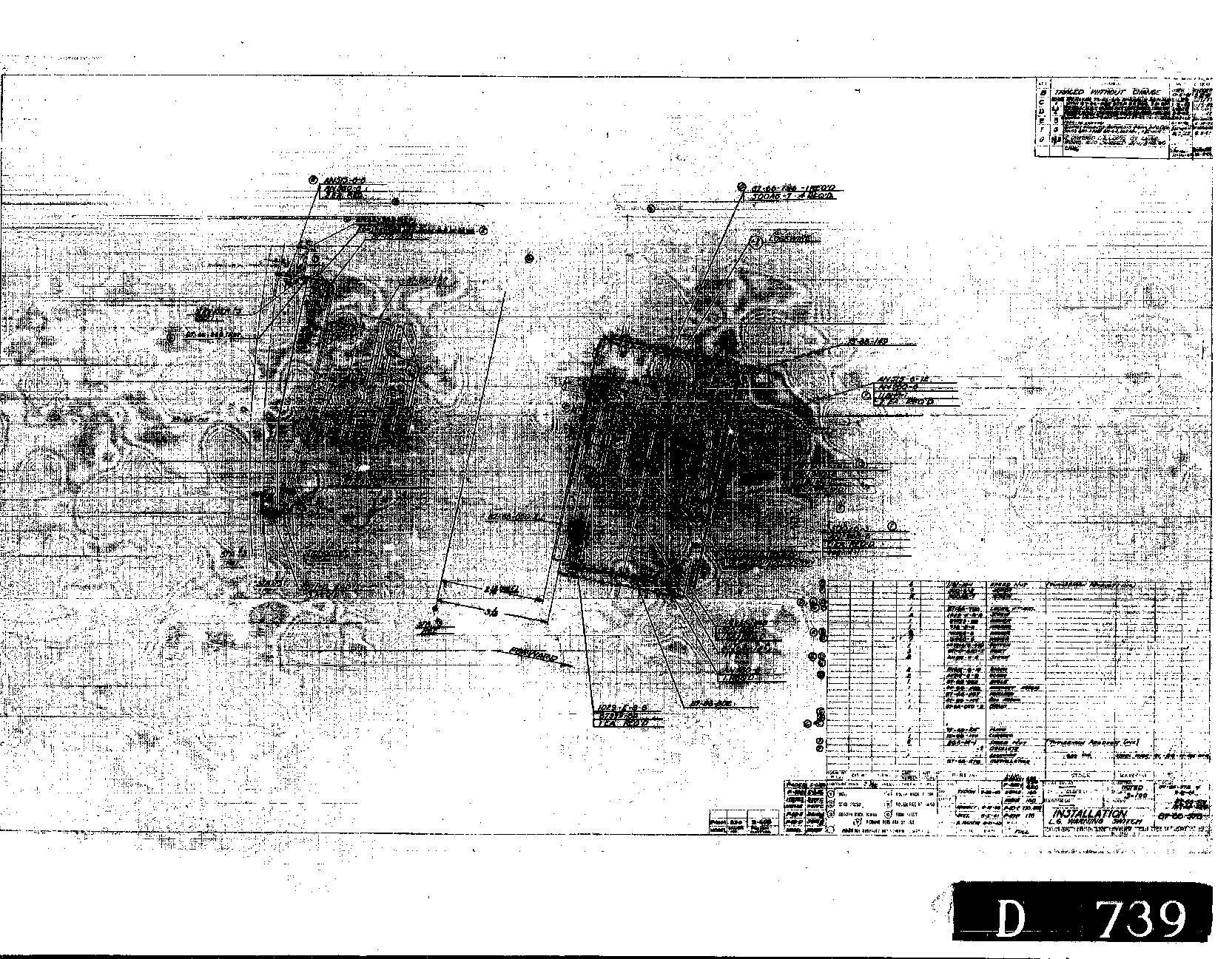
87-66-578 |
Switch - Landing gear warning |
1 |
|
| 85 |
14 |
|
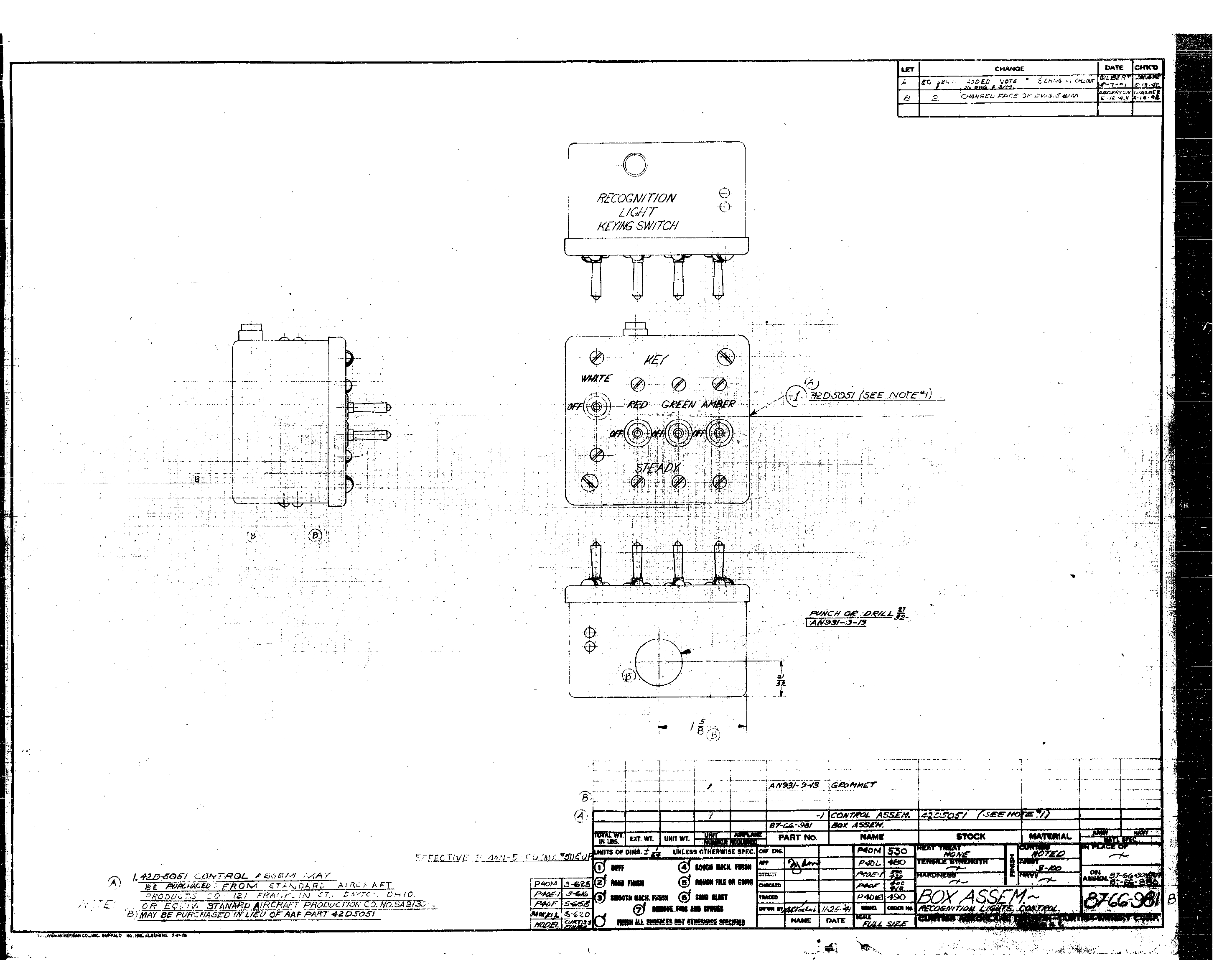
87-66-981 |
Box - Recognition light control |
1 |
|
| 85 |
15 |
|
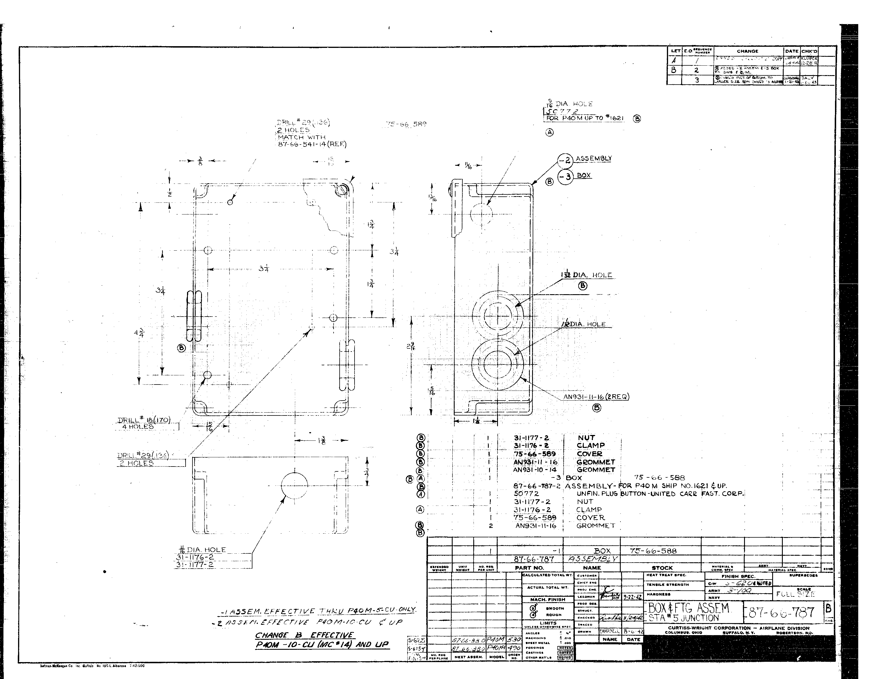
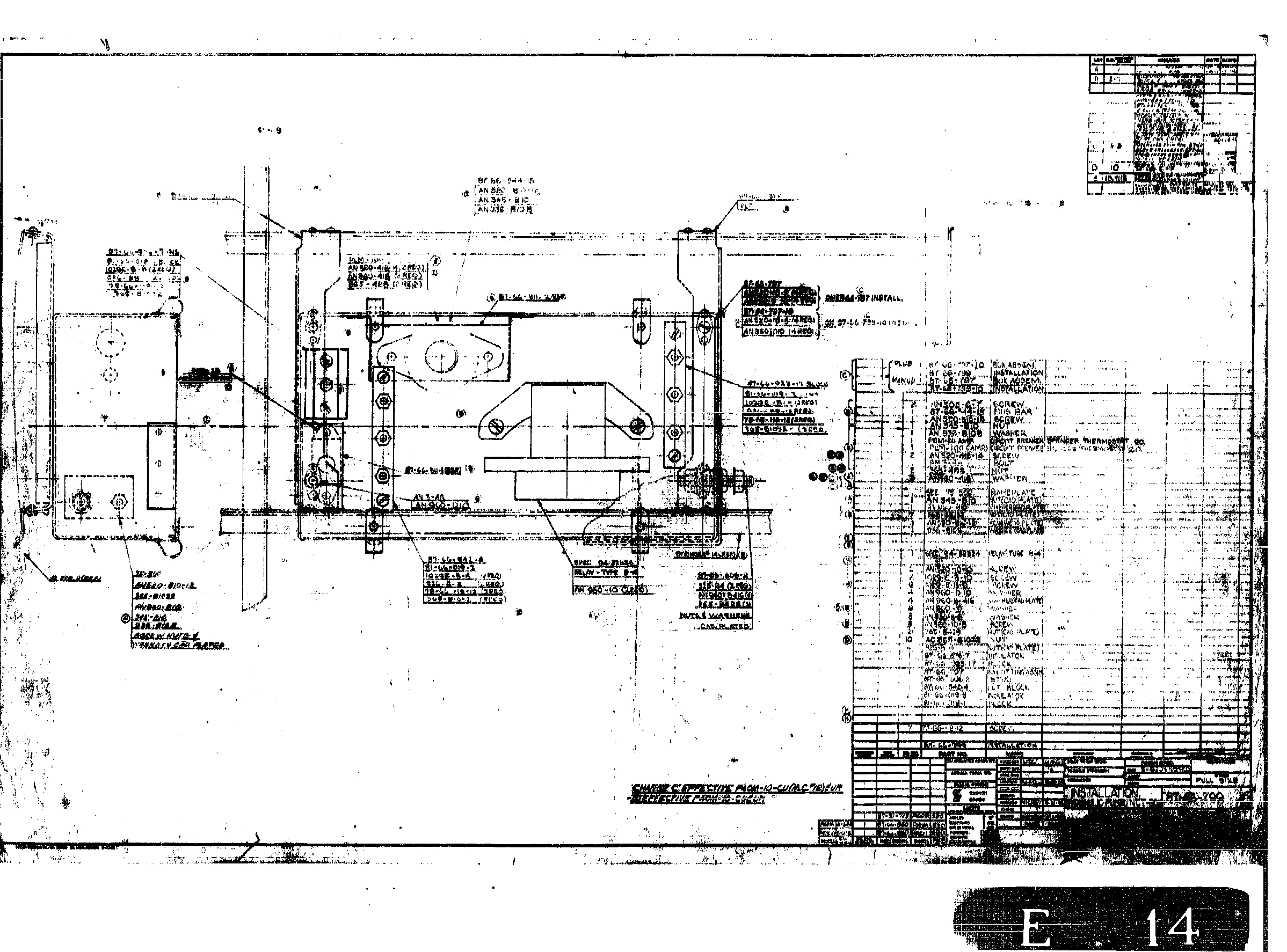
87-66-787 |
Box Assembly - Junction station number 5 |
1 |
|
| 85 |
16 |
|
87-66-799 |
Box - Hydraulic pump junction A |
1 |
|
| 85 |
17 |
|
87-66-799-10 |
Box - Hydraulic pump junction B |
1 |
|
| 85 |
18 |
|
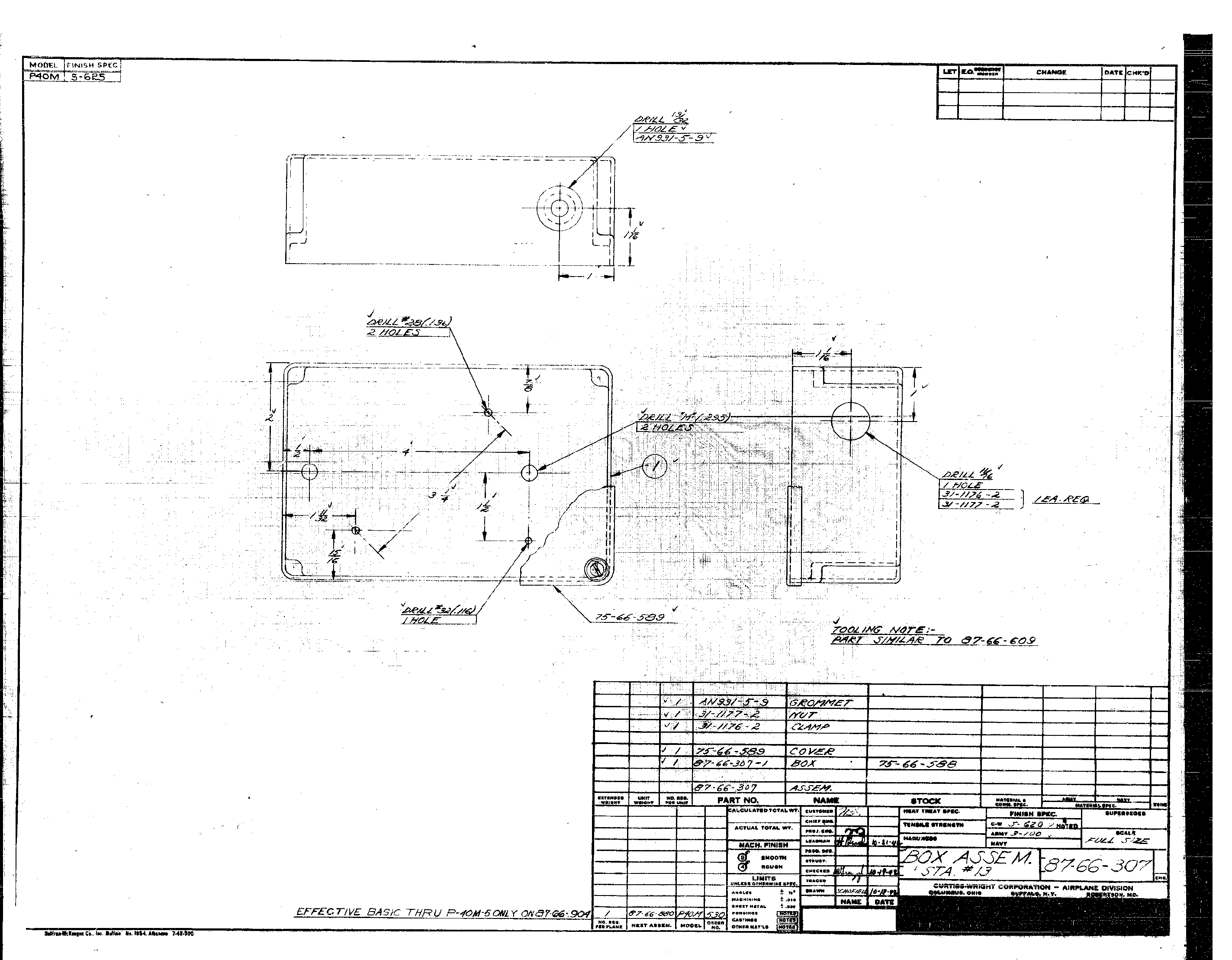
87-66-307 |
Box Assembly - Station number 13 |
1 |
|
| 85 |
19 |
|
87-66-082-6 |
Box - Retracting motor switch |
1 |
|