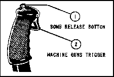
Figure 16 - Control Stick Grip
ARMAMENT
a. Three .50-caliber model M-2 machine guns mounted in each wing panel.(1) Guns fire at full automatic rate.(2) Normal load: 1,410 rounds (235 rounds per gun).
Overload. 1,686 rounds.
b. Gun Controls.
(1) All guns have to be loaded and charged before take- off. A manual gun charger is stowed on each gun bay door. Refer to the instructions on the gun bay door for procedure for charging the guns.
WARNING. Before starting the engine on flights which require the use of the guns, the pilot must be sure that the guns are charged.(2) The guns are electrically fired by depressing a trigger switch located in the handgrip of the flight control stick. (See figure 16.) The trigger switch actuates a solenoid attached to the inboard side of the gun which starts the gun firing. The guns will continue firing until the trigger switch is released. The gun electrical circuit is controlled through a two position ("ON" or "OFF") safety switch (figure 5) located on the left side of the main control switch panel. A short circuit in the gun sight electrical system will cause the gun electrical circuit to become inoperative. However, this difficulty may be removed, by turning off the gun sight rheostat, and resetting the circuit breakers (figure 5) on the right side of the main switch panel to the "ON" position. The guns will again become operative.

Figure 16 - Control Stick Grip
Throw the gun circuit breakers and the gun safety switch to the "ON" position. Depress the trigger switch and hold for the desired burst of gunfire.CAUTION: ALWAYS RETURN THE GUNSAFETY SWITCH TO THE "OFF" POSITION BEFORE LANDING THE AIRPLANE. FAILURE TO FOLLOW THIS PRECAUTION MAY RESULT IN THE GUNS BEING FIRED UNINTENTIONALLY BY DEPRESSING THE GUN TRIGGER SWITCH INSTEAD OF THE LANDING GEAR SWITCH (figure 10) WHICH IS LOCATED NEAR THE BASE OF THE HANDGRIP ON THE CONTROL STICK.
a. Three 20-pound type M-42, or three 30-pound type M- 5 fragmentation bombs, or three 20-pound type M-45 practice bombs may be carried under each wing panel outboard of the machine guns.(1) Bomb Release. - The bomb release quadrant, type L-21A (wing bombs) is located left of the pilot's seat and between stations No. 3 and No. 4.
(a) Electric selective release of the bombs is accomplished as follows: Move the release lever on the bomb control assembly marked "R" from the "'LOCK" to the "SELECTIVE" position; move the arming lever marked "A" to either the "SAFE" or "ARMED" position as desired; then turn the bomb safety switch "ON" and depress the button-type switch in the top of the handgrip on the control stick. (See figure 16.)
(b) Salvo. - The bombs are released in salvo only by raising the safety latch on the bomb release lever marked "R" and pushing the lever forward to "SALVO" position. The arming lever marked "A" may be in either the "ARMED" or "SAFE" position as desired.
b. Any of several different types of bombs ranging in size from 100 pounds to 600 pounds may be carried in place of the belly fuel tank below the wing panel.
(1) Bomb Arming Handle (Belly Bomb). - The bomb is armed by pulling up on the bomb arming handle located at the left of the pilot's seat. The bomb may be resafetied by returning the arming handle to the down position.
(2) Bomb Tank Release. - The bomb is released by pulling up on the bomb-tank release located at the lower left side of the cockpit, attached to the aft side of station No. 3 bulkhead.
The type N-3A gun sight with a modified reflector holder is mounted near the top of the instrument panel. The gun sight is equipped with an electric lamp which is controlled by a switch integral with the rheostat that controls the intensity of the light on the gun sight reflector. The rheostat is located near the center of the main electrical control switch panel.
A type N-2 camera, is mounted in right wing landing gear knuckle. On airplanes prior to AF42-10180 an overrun control is installed. The overrun control is a separate unit mounted on a bracket on the left side of the cockpit, outboard of the landing gear control handle. The function of the overrun control is to keep the camera running after release of the trigger switch, for a period of time indicated by its dial. This dial may be set for any period between 0 and 3 seconds in 1/20 increments. A small pin mounted on a magnet acts as an overrun indicator. The pin is magnetically retracted from the picture aperature when the trigger switch is closed and inserted into the aperature when the switch is released. Hence, the indicator shows in the picture during the period the camera runs via the overrun device and records the exact instant the gunner ceases firing. The overrun control is actuated by a switch on the top of the control box.