|
(2) Finishing Method. (a) As the second coat of Linatex is applied, care should be taken in lapping the applied pieces so that the laps made in the first and second coverings are staggered. This gives a maximum thickness of three layers of Linatex in any one spot, and keeps irregularities in the contour at a minimum. (b) In applying the cements and primer, spraying may be used for applying primer C-10. The coat of cement L-U0 may be applied by a dipping operation. Solufix No. 1 is best handled by brushing and gives the desired thin, smooth coats. Spraying of Solufix No. 1 is not recommended as the cement must penetrate the surface of the Linatex ln order to form good joints. (c) Butt joints formed by cementing the clean edges of sheets with Solufix No. 1 have nearly the full strength of the material. It is suggested, in order to conserve material, that large scrap pieces of the Linatex be butt jointed together to procure large sheets for use as covering. These butt joints may be for med by coating each clean edge with Solufix No. 1, allowing to dry 10 to 15 minutes, then placing the edges approximately 1/32 inch apart on a flat surface, and hammering the joint starting from one end and working toward the other. The Linatex expands sldewlse upon impact and cements, pulling the joint together. The edges must be trimmed true to match before cementing. (d) The duck used for the finishing coat over the Linatex is (16-3/4 oxmces) cotton duck proofed on one side only with masticated or uncured rubber in order to allow cementing over Linatex with Solufix No. 1 cement. When doping this duck, light coats should be applied to avoid excessive strain on the fabric and the cemented joints. The tanks should stand 2 days after covering before doping to allow the cements to dry and cure properly. (3) Tools and Materials Required. - Linatex is used in conjunction with special cements developed for use with this product. Two tools are used in rolling down the layers after applying to the oil tank. The first, a stitcher is used in rolling down the edges of lapped joints to form a secure joint without trapped air bubbles. The second is a small roller used on the entire surface toroll down the Linatex driving out the trapped air and insuring good contact between the cemented layers. f. Repair of Aluminum Tanks and Shells. - The coolant expansion tank, oil tank and the auxiliary hydraulic tank are of aluminum-alloy (3S) construction and can he repaired by welding. Before proceeding with welding operations, the tank must be free from dirt, oil, paint, etc. and all fittings must be removed. Run a constant stream of boiling hot water entering at the bottom of the tank and letting it overflow at the top for at least 1 hour. Blow compressed air into the tank until all odors have been expelled. |
g. Repair of Coolant Header Tank P-40F. (1) Minor Repairs. -Repairs such as small leaks, leaks around rivets, leaks around thermometer adapter housings and external reinforcing rings may be accomplished with a class 1 silver solder, Army Specification No. QQ-S-561C. The melting point of this solder is 675c (l250°F) and the flow point is 745°C (l370°F). (2) Major Repairs. - Repairs to larger holes requiring the application of a patch may be made as follows: Smooth the damaged area by filing off the rough edges with a file and then using emery cloth. Avoid as much as possible the bits of brass and filings falling into the header tank. The repair patch should be of the same gage as the tank skin and should be of sufficient area to overlap the damage a minimum of 3/8 inch. In soldering the patch to the skin use a class I silver solder, Army Specification No. QQ-S-561C. Before soldering, all surfaces must be thoroughly cleaned. A flux coat is then applied to the patch and to the header tank at the point of repair to protect against oxidation and to aid the flow of the solder. Powered borax mixed with water to form a thick paste is a good flux. Great care should be taken in applying the torch to the tank so as not to burn the metal. Use a gentle flame to heat the work to the required temperature before applying the solder. When the solder is brought under the flame of the torch it should melt and flow rapidly along the joint. After repairing, test the tank to a pressure of 40 pounds per square inch for leakage and strength of repair. h. Welding Procedure, - When welding aluminum tanks or shells, use oxyhydrogen flame according to instructions given in section I, paragraph 6.b. A 5 percent silicon rod, or equivalent, should be used with Flux No. 22, manufactured by the United States Aluminum Company. The flux is mixed with water to a thin paste condition and is applied on the area to be welded and also for dipping the rod. Cut all fractures round or elliptical and when these openings are closed, the tank edges should be bumped up about 1/2 inch and the patch to be inserted should also have upturned edges to fit snugly into the tank opening. The patch can then be tacked and welded in place as shown in the following sketch. 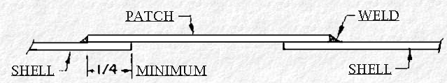 If the tank thickness of the metal is .050 inch or over, a lap weld patch as shown, may be used, provided there is room for the repair. 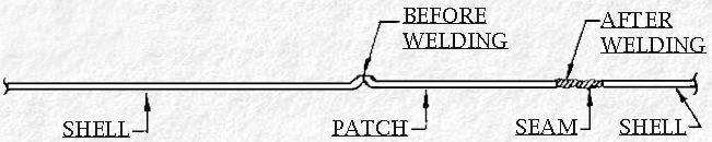 |
